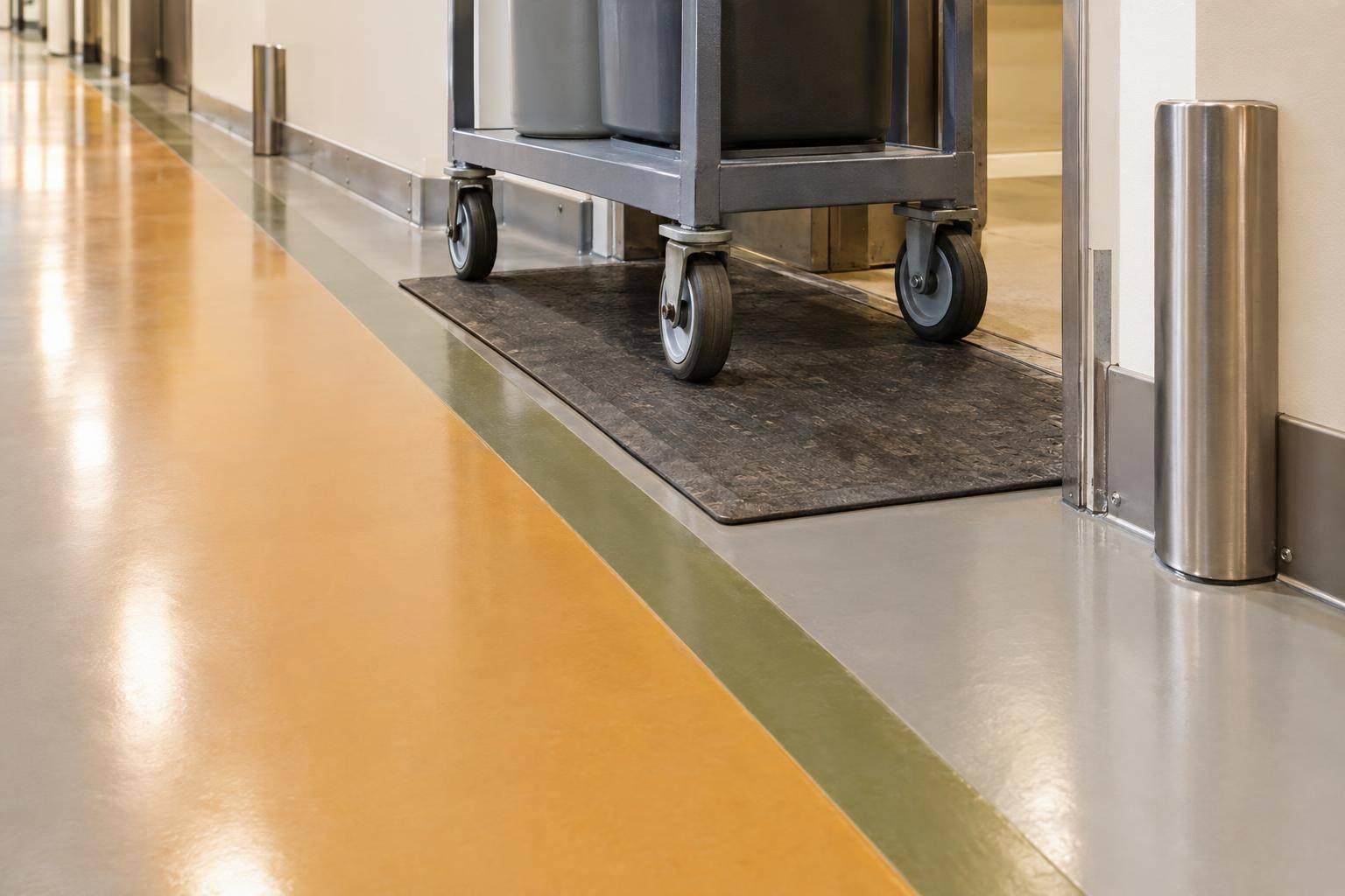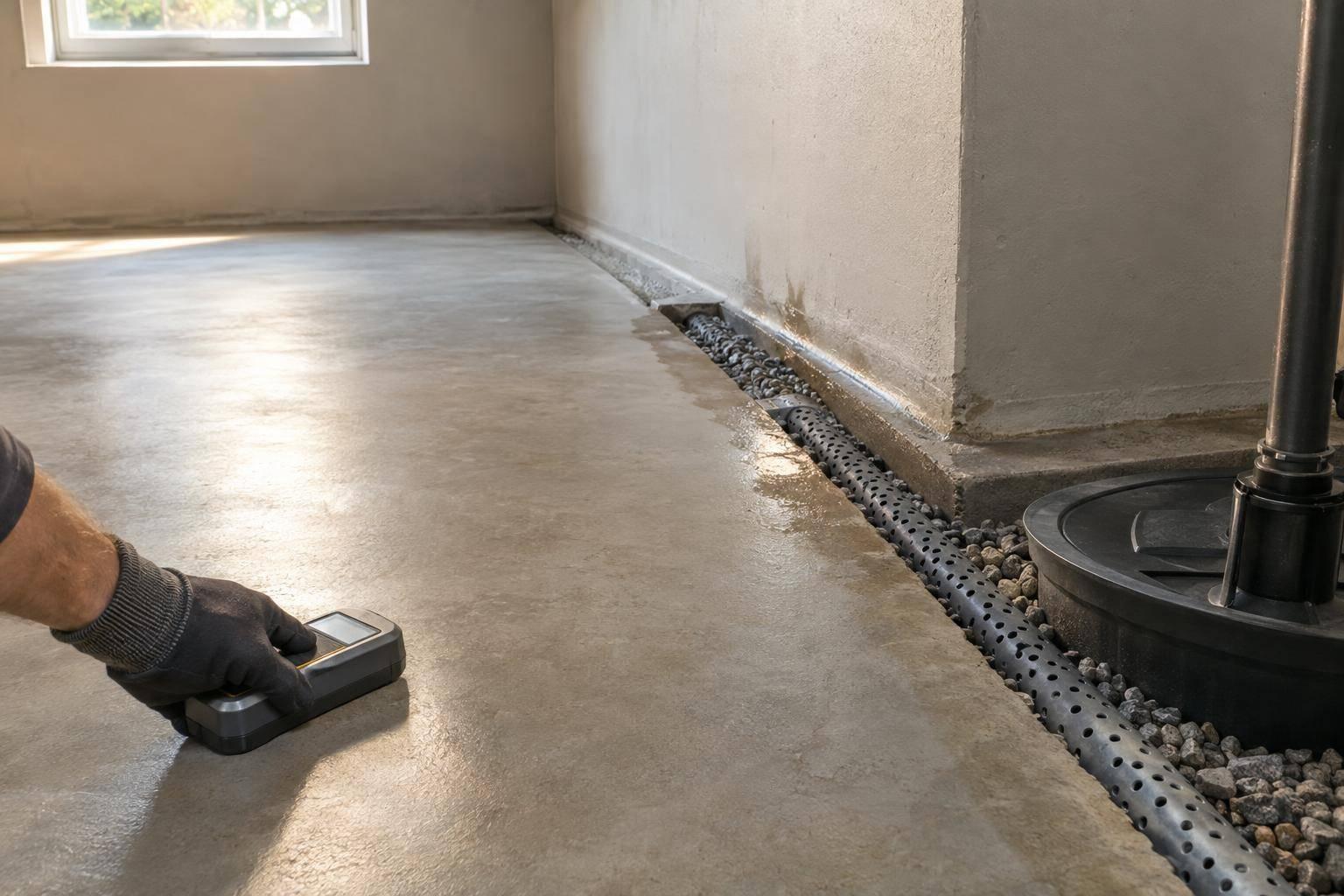
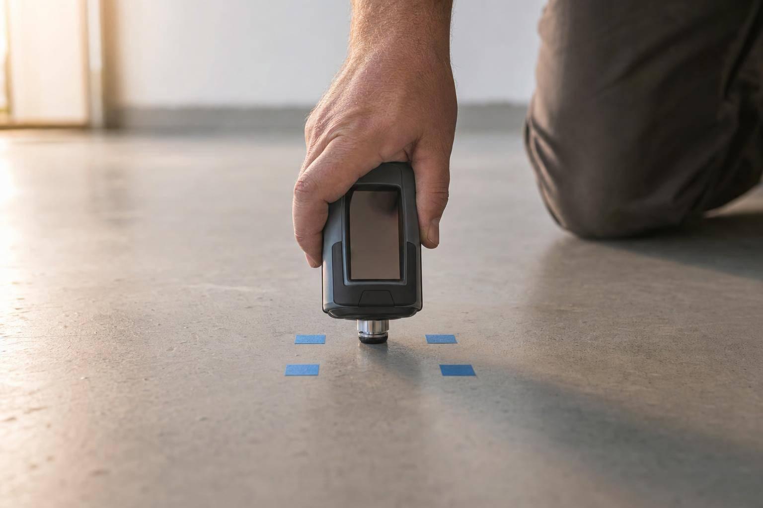
If you want to know whether a concrete floor coating was applied right, measure its dry film thickness (DFT) after cure. On concrete, the main non-destructive tool is an ultrasonic gauge. You should test a clean, fully cured floor, take 3 to 5 readings per spot, use at least 5 spots per area, and compare your averages to the product spec. For example, if a floor is specified at 12 to 15 mils, readings far below that range can mean early wear, common epoxy floor problems, while readings far above it can lead to cure and coating failures.
Here’s the short version:
- DFT matters most because it affects wear, stain resistance, and warranty terms.
- Magnetic gauges do not work on concrete because concrete is not metal.
- Ultrasonic gauges are the standard choice for non-destructive checks.
- Cross-section checks are used when you need to confirm a reading, but they damage the coating.
- Test by zone, not just in one easy spot.
- Average your readings instead of trusting one number.
- Flag odd readings and log them instead of deleting them.
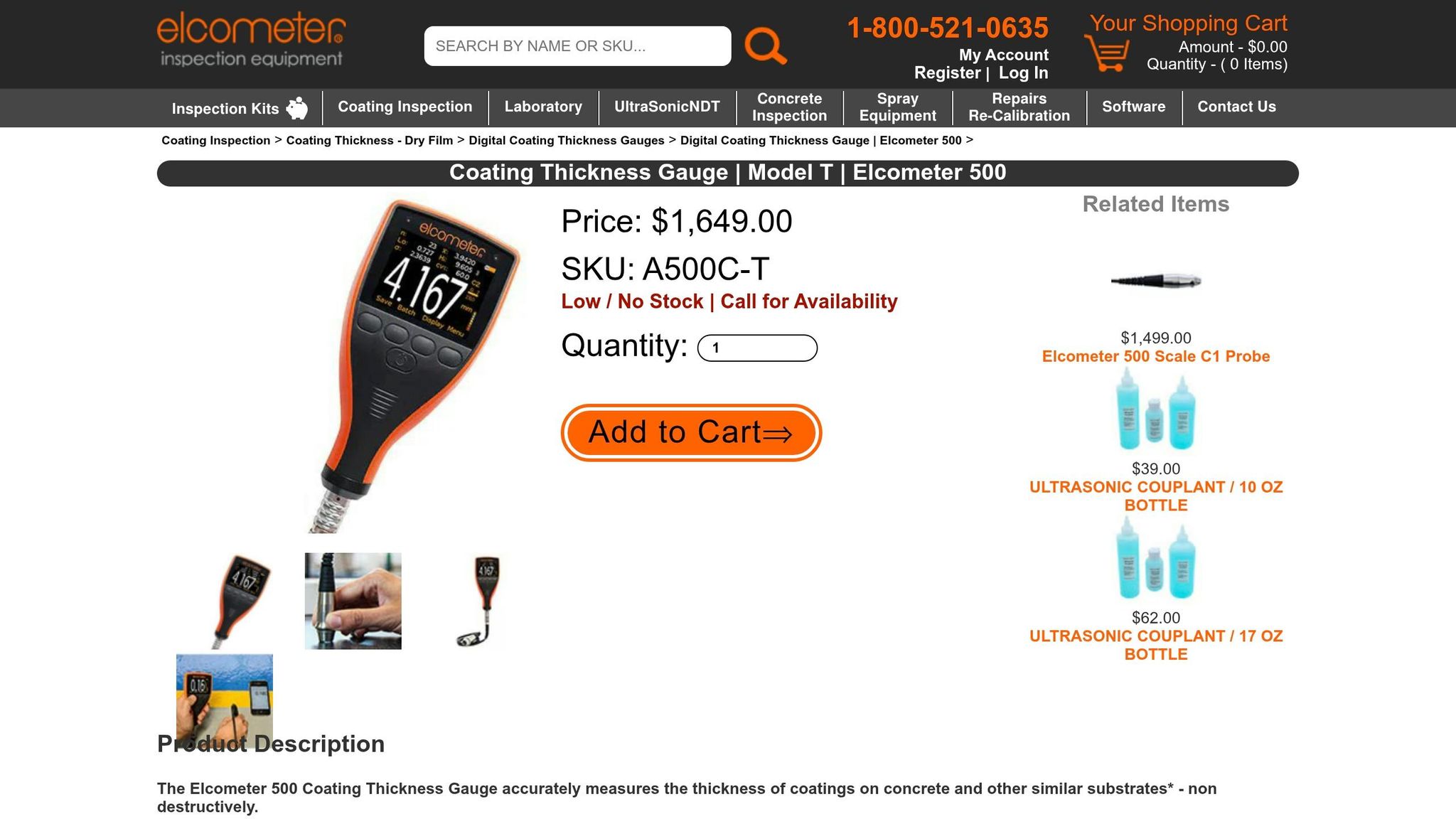
How to take accurate DFT measurements on concrete with the Elcometer 500 Coating Thickness Gauge
sbb-itb-a0e5ae3
Quick Comparison
| Method | Best use | Surface damage | Main note |
|---|---|---|---|
| Ultrasonic gauge | Routine floor checks | None | Best fit for large coated concrete areas |
| Cross-section check | Confirming thin or disputed areas | Yes | Very accurate at one cut point only |
I’d treat coating thickness as a simple pass-or-fail check: use the right tool, test enough spots, log the numbers, and compare them to the stated mil range before you sign off on the floor and begin maintaining your concrete coatings.
Choose the right tool for measuring coating thickness on concrete
Concrete is non-metallic, so the magnetic and eddy-current gauges you’d use on steel simply won’t work here. That makes tool selection the first thing to get right if you want a dependable DFT reading on concrete.
Ultrasonic gauges for non-destructive readings
Ultrasonic pulse-echo gauges are the main non-destructive option for this job. The probe sends a high-frequency pulse through the coating, then picks up the echo from the coating-concrete boundary. The gauge measures the round-trip time-of-flight and converts that into a thickness reading based on the coating’s sound velocity.
Getting solid readings comes down to three basics: calibration, couplant, and probe setup. Calibrate the gauge for the exact coating system you’re testing, use the couplant the manufacturer recommends for that surface, and keep the probe flat and perpendicular with light, steady pressure. On smooth, horizontal surfaces, water can work as a couplant. On rough or vertical surfaces, a gel like propylene glycol is often the better pick. You’ll also want a gauge rated for the coating thickness range you need to check.
When to use a cross-section check
Use a destructive cross-section check only if ultrasonic readings don’t line up or if you need to confirm a thin area. This method means cutting through the coating down to the concrete, then measuring the exposed layer directly with a caliper, microscope, or optical gauge. It gives a very accurate result at that one spot, but there’s a tradeoff: the coating is permanently damaged and must be patched.
If you do make a cut, pick a low-visibility area, such as along a wall, behind equipment, or in a corner. That helps limit cosmetic damage.
Ultrasonic gauges vs. cross-section tools: a side-by-side comparison
| Feature | Ultrasonic Gauge | Cross-Section Check |
|---|---|---|
| Method | Pulse-echo sound measurement | Physical cut and direct measurement |
| Typical use | Routine inspection across large floor areas | Verification, troubleshooting, dispute resolution |
| Accuracy | High when properly calibrated | Very high at the cut location |
| Impact on coating | Non-destructive | Destructive; requires patching |
For routine floor inspection on concrete, ultrasonic gauges are the clear pick. They’re fast – some models can take 140+ readings per minute in scan mode – non-destructive, and well suited for checking large floor areas in a short amount of time.
Once you’ve picked the tool, the next step is inspecting the concrete and choosing test spots that reflect the whole area. Proper surface preparation ensures these readings reflect a high-quality bond.
Prepare the floor and select the right test spots
Good readings start with a cured, clean surface and a clear test plan. After you’ve picked the gauge, get the floor ready so each reading reflects the cured coating, not dirt on the surface or bad probe contact.
Check cure condition, surface cleanliness, and couplant
Surface contamination and incomplete cure can throw off ultrasonic readings. Make sure the coating is fully cured before you measure. A film that’s only partly cured can still shrink or shift in density, and that can distort the result. Follow the cure schedule and test only when the film is hard, not tacky.
Clean the floor, then let it dry all the way before testing. Dust, debris, moisture, oil, polish residue, and curing compounds can all weaken the signal.
Pick a thin couplant for smooth floors and a thicker gel for rough or porous areas. Apply a thin layer, keep the probe flat, and wipe off any residue after testing.
Once the surface is ready, map the floor so your readings cover the whole area, not just the easiest place to reach.
Divide the floor into zones and pick representative spots
Your test zones should match how the floor is used, because thickness can change across high-traffic and repaired areas. Don’t bunch readings into one convenient spot. Split the floor into zones based on use, such as:
- parking
- drive paths
- thresholds
- entries
- aisles
- loading areas
Within each zone, pick evenly spaced test spots, then add extra readings in the highest-wear locations. Focus on wheel paths, turns, and thresholds, where wear tends to be highest. Measure repaired or patched sections on their own; they often differ from the surrounding field. Use at least 5 readings per area and average them to show normal variation across the slab.
Record the location of each reading, the zone, the surface condition, the couplant used, and anything unusual, like roughness, moisture, or repairs. Then use that map as you take and log readings.
How to measure coating thickness step by step and record the data
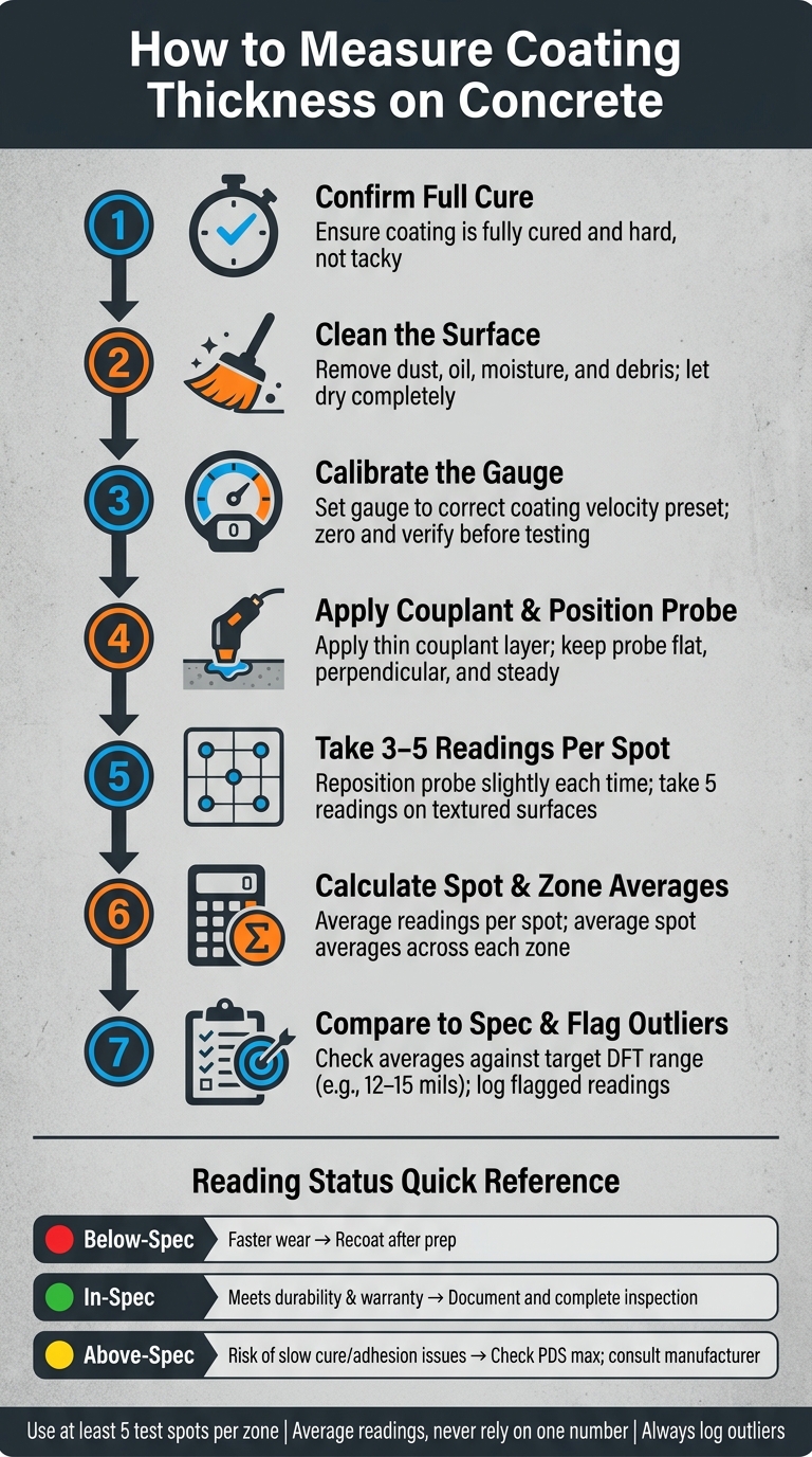
How to Measure Coating Thickness on Concrete: Step-by-Step Guide
Use your zone map to take readings, then log each one right away. Stick with the same zone map and the same spot order every time. If you shift probe placement or write down a value in the wrong place, the inspection results can get skewed fast.
How to take readings with an ultrasonic gauge
Set the gauge to the coating preset or velocity before you start. If that setting is off, the gauge will give you a wrong thickness reading every time, even when probe contact looks perfect. Zero the gauge and verify it before testing.
Apply a small amount of couplant, keep the probe flat and steady, and wipe the surface after each spot. Press gently until the gauge gives a valid reading, usually a beep or a steady number on the screen. Then lift the probe to lock in the reading and record it.
Take at least three readings at each test spot. Reposition the probe slightly each time, but stay within the same spot area. On heavily textured surfaces, take five readings.
Average your readings and flag unusual results
Work out the spot average by adding the valid readings and dividing by the number of readings taken. Then work out the zone average by averaging the spot averages across a defined zone, such as a full bay.
If one reading is far from the others at the same spot, stop and look at that location. Check for voids, surface defects, or contamination. Then retake the measurement. If the odd value shows up again and you can see a physical reason for it, mark it on your floor plan as a localized issue and log it as flagged instead of quietly tossing it out. Outlier readings should always go in the record, even if you leave them out of the zone average, so the inspection trail stays clear and auditable.
Spot readings vs. zone averages: what each one tells you
A single reading shows what is happening at one exact point. A zone average shows how the floor is performing across an area. On concrete, surface texture, porosity, and repair patches can cause real variation, so one reading by itself is not enough for an acceptance decision.
| Metric | How it is calculated | When it is used | What it means for acceptance |
|---|---|---|---|
| Spot reading | Single gauge value at one probe position | Scanning suspect areas: joints, drains, traffic lanes | Localized only |
| Spot average | Mean of 3–5+ valid readings at one test spot | Comparing a location to the specified min/max range | Primary acceptance unit |
| Zone average | Mean of all spot averages within a defined zone | Judging overall floor compliance and supporting warranty documentation | Overall zone compliance |
Use spot averages for local checks and zone averages for zone compliance. Next, compare those averages with the specification and tolerance range.
Read the results and decide what they mean for floor performance
Use the zone averages and any flagged outliers from the last step to decide if the floor meets spec. Check your spot and zone averages against the project spec, the product data sheet, and the warranty terms. Each one matters for a different reason.
The spec gives you the target DFT and the allowed tolerance. The PDS tells you how film build affects performance. The warranty spells out the thresholds tied to coverage. Thickness isn’t just a reading on a gauge. It affects how the floor performs and whether it stays within warranty terms.
At this stage, you’re doing a simple pass-fail check against the written requirements.
Compare your readings with the specification and tolerance range
Start with the zone averages. Each zone average should fall within the target range. Then look at spot averages. If a spot average falls outside the alert range, treat it as a problem area.
For example, if the specification calls for 12–15 mils DFT, spot averages should stay between 9.6 mils and 18 mils.
Pay extra attention to high-traffic zones. If readings bunch up near the minimum in wheel paths or entry lanes, that deserves a closer look. Those areas usually wear out first.
What below-spec, in-spec, and above-spec readings mean in practice
Below-spec thickness means less wear, chemical, and stain resistance. It also shortens service life. Thin areas in wheel paths or entry lanes are often the first to fail. The usual fix is spot recoating or a full added coat after proper surface preparation.
Above-spec thickness can slow cure, trap solvents, and put stress on adhesion. Check that the readings stay under the PDS maximum for each coat.
In-spec readings mean the coating meets spec and should meet durability, slip, chemical, and warranty requirements. When you document zone averages and minima, both the installer and the customer have a clear record showing that the floor meets the published film-build requirements.
Use the table below to match each reading status to the next step.
| Reading Status | Likely Floor Behavior | Recommended Next Step |
|---|---|---|
| Below-spec | Faster wear, lower resistance, shorter service life | Recoat after prep; correct before the system is considered complete |
| In-spec | Meets spec; complies with durability and warranty requirements | Complete final inspection; document zone averages and minima |
| Above-spec | Possible slower cure, tacky surface, or adhesion stress | Check PDS maximum DFT; consult manufacturer if readings exceed published limits |
For Croc Coatings‘ garage floors, patios, and commercial spaces, meeting the specified DFT is what separates a floor that holds up for years from one that starts showing wear too soon. The numbers on your gauge matter only if you know how to act on them.
FAQs
When should I measure coating thickness on concrete?
Measure coating thickness before, during, and after installation to help support performance and warranty compliance.
Check thickness during planning so you can estimate how much material the floor needs based on its condition and how it will be used. Then measure again during and after application to make sure the coating matches manufacturer specs.
If you start to notice wear or changes in how the floor performs, test it again.
How accurate are ultrasonic thickness readings on rough concrete?
Ultrasonic thickness readings aren’t automatically reliable on rough or textured concrete. Surface bumps and uneven spots can get in the way and throw off the measurement.
For results you can trust, the concrete surface needs to be ground smooth before testing. Peaks and valleys can distort the reading, so a flat, even surface is key for precise, repeatable measurements.
What should I do if some areas measure out of spec?
First, compare your measurements with the manufacturer’s technical specifications. If the coating is too thin, the concrete may be left exposed. If it’s too thick, the coating can turn brittle or crack.
If you’re dealing with a small trouble spot, a spot repair may do the job. But when problems show up across a larger area, it’s smart to bring in a professional. They can pinpoint the cause, whether that’s poor surface prep, moisture, or application mistakes.
Keep photos and written records, too. That paper trail helps with warranty compliance and makes repair planning a lot easier.